![]()
About the company |
|
Fields of activity |
|
References |
|
Contacts |
|
|
|
|
About the company |
||
|
|
Fields of activity |
||
|
|
|
Production |
|
|
|
|
|
Plate Heat Exchangers |
|
|
|
|
Gasketed PHE |
|
|
|
|
Brazed PHE |
|
|
|
Modular Heat Substations |
|
|
|
|
Boilers |
|
|
|
|
Regulators |
|
|
|
|
Oil Cleaning |
|
|
|
|
R&D |
|
|
|
References |
||
|
|
Contacts |
||
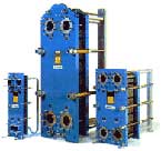
GASKETED PLATE HEAT EXCHANGERS
The Standard Construction
In a Gasketed Plate Heat Exchanger (frame & plate heat exchanger), the plates are fitted with elastomeric gaskets which seal the channels and direct the fluids into alternate channels.
The plate pack is assembled between a frame plate and a pressure plate, and compressed by tightening bolts fitted between these plates. The channel plates and the pressure plate are suspended from an upper carrying bar and located by a lower guiding bar, both of which are fixed to the support column. The physical design of the gasketed plate heat exchanger allows easy cleaning and modification of capacity by addition or removal of plates.
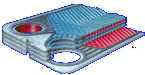
The most commonly used plate material is stainless steel AISI 316. Titanium plates are used for media containing chlorides e.g. sea water. Exotic materials such as Hastalloy, Incoloy and graphite are available for chemical processing duties. The thickness of plates is normally in the range of 0.4 - 0.7 mm.
The connections for media inlet and outlet can be located on the frame or on the pressure plate. Various channel plates styles are available, corrugated in different patterns, suitable for a large number of fluids and a wide range of thermal duties.
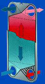
Principle of operation
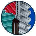
The fluids taking part in the heat transfer process are introduced through the connections to the Heat Exchanger. The gaskets, fixed in a special way, provide the fluids distribution to the proper channels, excluding the possibility of mixing the flows. The plate corrugation type and channel configuration is selected according to the required duties, and it ensures the optimal conditions for the heat exchange process.
Technical Data:
| Gasketed PHE type | M3 | M6 | M6M | M10B | M10M | M15B | M15F | M20 | M30 |
| Max. fluids flow rate, kg per sec | 3,8 | 15 | 15 | 50 | 50 | 60 | 80 | 250 | 500 |
| Max. heat transfer area, m2 | 3,9 | 38 | 38 | 105 | 62 | 295 | 390 | 940 | 1335 |
| Max. operating temperature, °С | 130 | 130 | 160 | 150 | 160 | 160 | 160 | 150 | 150 |
| Max. operating pressure depending on the frame type, MPa | 1-1,6 | 1-2,5 | 1-2,5 | 1-2,5 | 1-2,5 | 1-2,5 | 1-2,5 | 1-2,5 | 1-2,5 |
The range of Alfa Laval heat exchangers is not limited to the units types mentioned in this table.
Standard sizes:
The conventional Plate Heat Exchanger design .
| Sizes | A | B | C | D | E | F | The size of connection pipes according to DIN |
| M3 | 180 | 60 | 480 | 357 | 62 | 204-500 | 32 |
| M6 | 320 | 140 | 920 | 640 | 140 | 580-1430 | 50 |
| M6M | 320 | 140 | 920 | 640 | 140 | 580-1430 | 50 |
| M10B | 470 | 225 | 981 | 719 | 131 | 710-2310 | 100 |
| M10M | 470 | 225 | 981 | 719 | 131 | 710-2310 | 100 |
| M15B | 650 | 298 | 1815 | 1294 | 275 | 1170-3270 | 150 |
| M15F | 650 | 298 | 1815 | 1294 | 275 | 1170-3270 | 150 |
| M20 | 920 | 439 | 2895 | 1939 | 435 | 1585-3385 | 200 |
| M30 | 1150 | 596 | 228 | 1842 | 470 | 1595-5195 | 300 |
[Top]